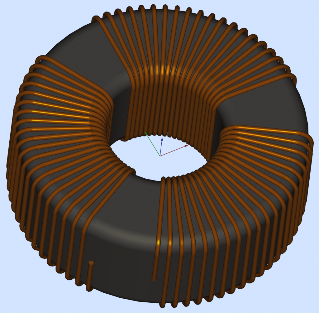
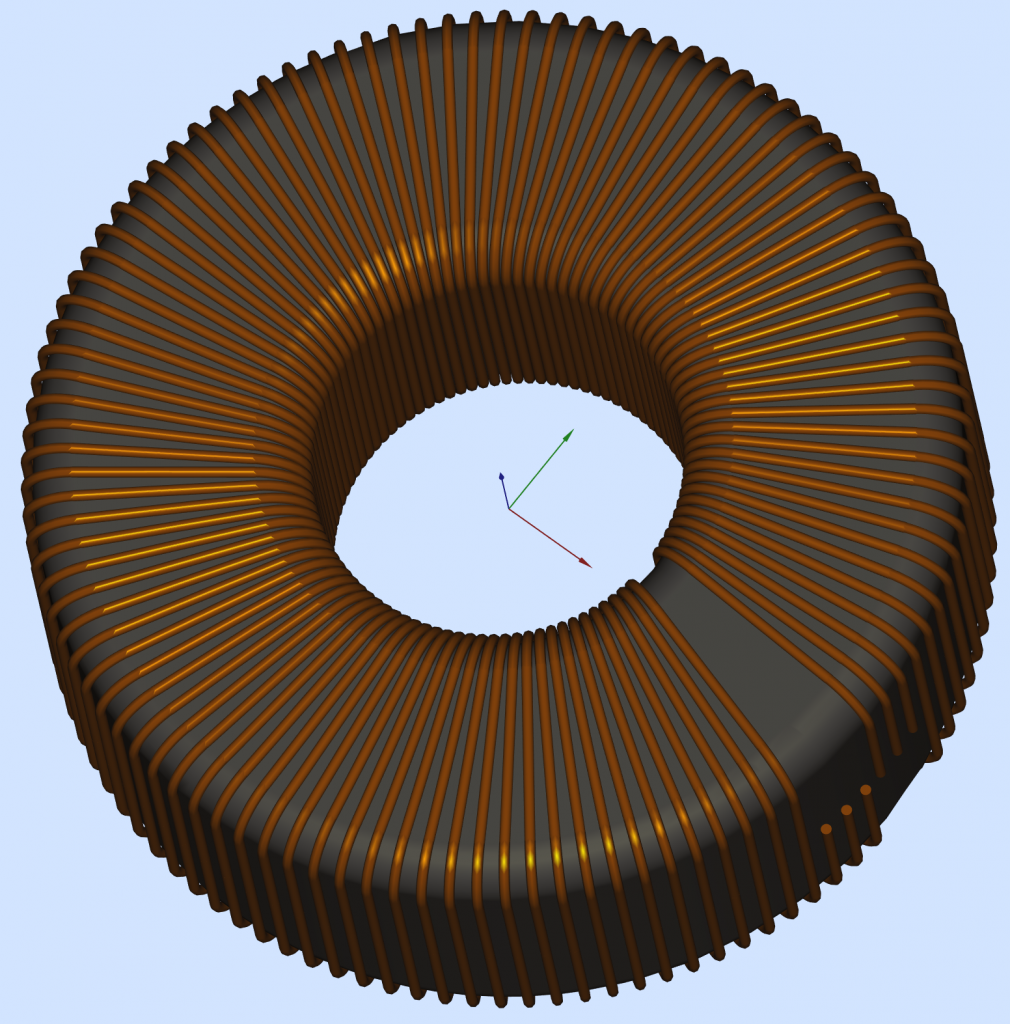
Finally, I completed my first 3D Toroidal Winding Project in FreeCAD, and I can use it for real work. Just changing a few numbers in a spreadsheet I can generate automatically and in only a few seconds pretty much any transformer configuration, up to 32 layers/windings, based on real spec-sheet core and winding wire parameters. With a bit of COPY/PASTE it is possible to add more winding layers, more windings in a layer, change independently the beginning/end angle of the windings, the winding pass, interleave or separate them, and so on.
What was so difficult you ask?
For starters, I had to learn a CAD program. And yes, FreeCAD has some impressive abilities; dealing with a bunch of Toroidal windings is not one of them, or at least it was not quite trivial starting with a Helix. There is a good tutorial on YouTube, and it helped me to understand the good and the not so good: https://www.youtube.com/watch?v=ou92FEz1lT0 . Without too much talking, the working projects can be found here:
How I did it?
The secret sauce I used to get a “perfect” 3D model was to avoid altogether the Helix beast and to describe the winding contour on the toroid based on only straight lines and perfect circles. Feeding FreeCAD with only this kind of elementary data proved to be the right medicine. Many thanks to chrisb and to drmacro from the FreeCAD forum, they clarified where I should look for problems. Now the size of the project file, the precision of the model, and the FreeCAD processing speed are quite ideal I would say.
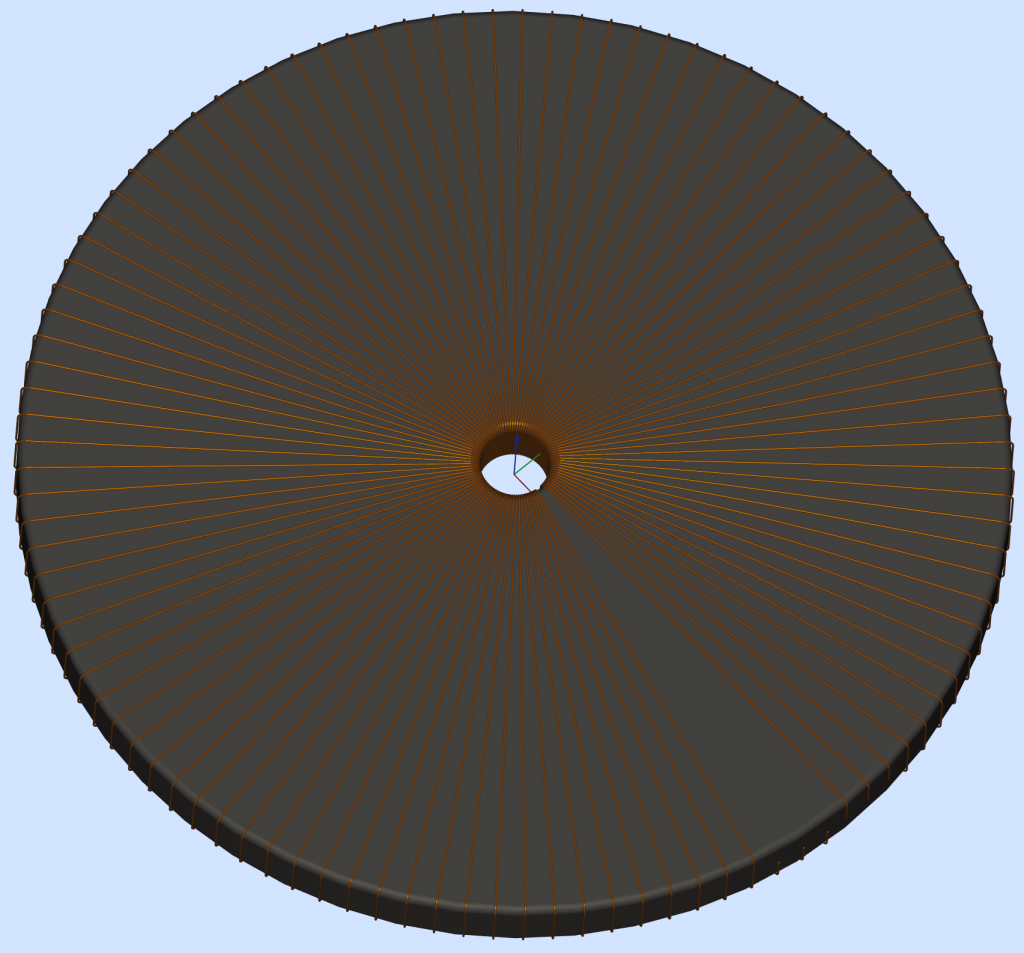
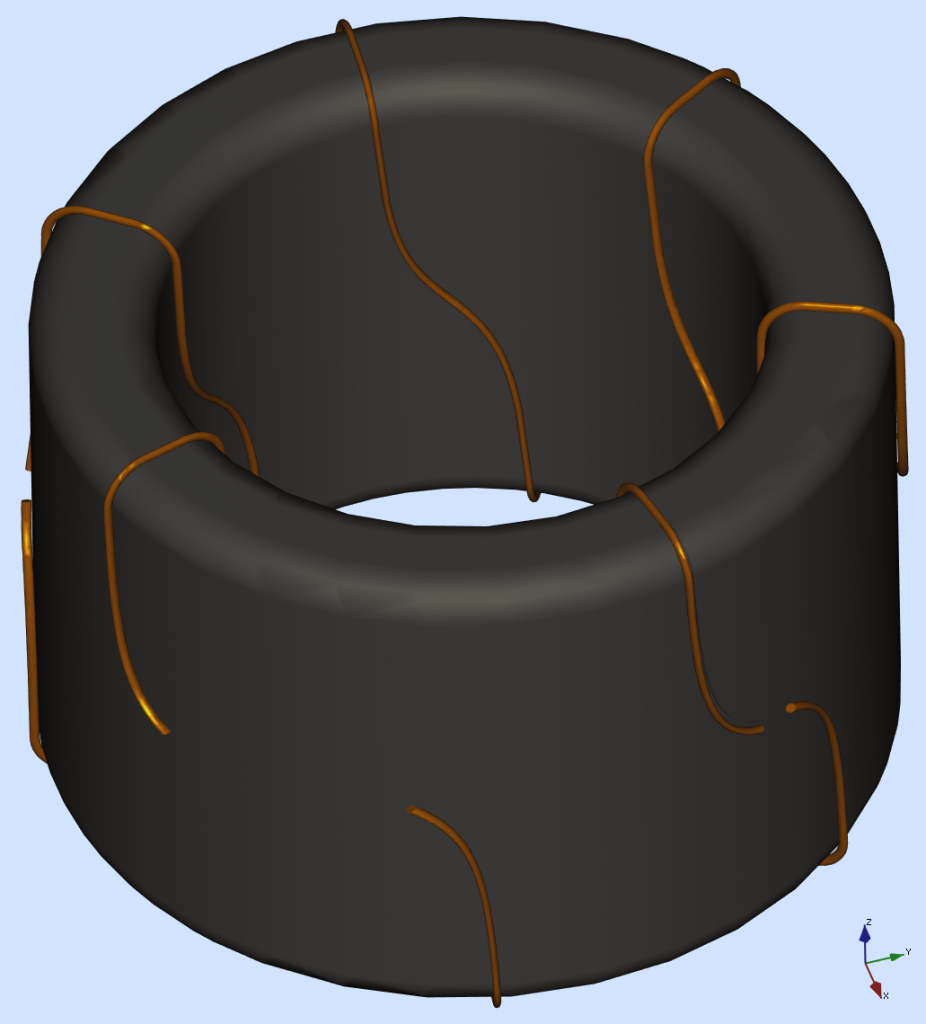
The winding head has guiding pads to keep the wire in a defined position, especially when the sliding belt or the shuttle are in the “recovery” arc. This winding technique will force the wire to follow a mostly vertical path on the outside or the inside surface, while the angle progression from turn to turn is mostly placed on the TOP and the BOTTOM surface of the Torus. The 3D model proposed here is using vertical planes arranged to mark the winding reference angles. The winding path traced on the vertical Torus surfaces will have vertical lines, and properly adjusted winding angles on the flat TOP and BOTTOM surfaces. The proper dimensions and angles will be retrieved from the SETdata spreadsheet.
It is true, the “real” winding has some angle added on the internal and external vertical faces too. For the reason explained before this angle dos not quite follows an ideal Helix, and my model can be amended to account even for this slight mismatch (using 4 slicing planes instead of only 2). A winding machine will always wiggle over those angles, I decided that my 3D model falls inside the nominal winding precision window.
After the real Torus was defined I needed to define a new and larger Torus to help draw the path of the winding wire, more precisely the path for the center of the wire cross section. If more than one winding layer is required it is possible to define more and incrementally larger Torus shapes, to account for filling-up the Torus with multiple layers.
What was wrong with the YouTube tutorial?
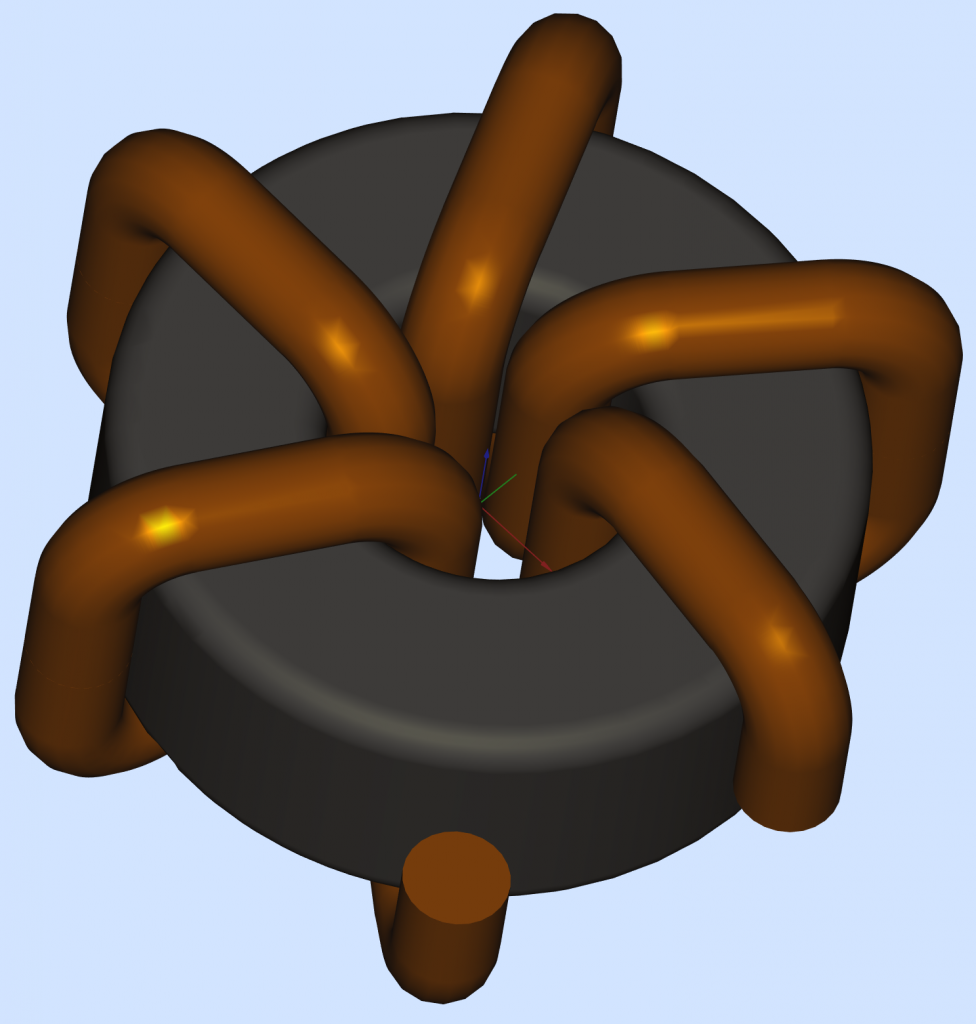
FreeCAD can easily create a Helix, but only if the Helix is progressing in a linear direction. Unfortunately, in order to place a Helical winding on a Torus you have to bend the Helix progression in a revolving way along the Torus. That, right there, is breaking the FreeCAD camel’s back: bending the Helix will dramatically increase the size of the FreeCAD project file, and the resulting shapes are kind of useless. Any attempt to further process those resulting shapes will crash the program after a looooong waiting time. And yes, poor FreeCAD will successfully check the geometry and it will report that everything is just peachy. The “work-around” used in the YouTube tutorial was to approximate a circular revolving Helix slice using a linear progressing Helix chunk. This choice works somehow, but only for “golden ratio” projects. As soon as one attempts to decrease the number of turns or to choose an unusual core size ratio, the 3D model kind of breaks down:

I saw your posts on the FreeCAD forum and am interested in using your FCStd file to create a model for a project I am working on.
this is not a commercial project, but just for hobby purposes.
It will be a transmission line transformer toroid and I will wind it
by hand. Only 14 turns of wire. Thank you Karin Johnson
Hi,
I posting something on the FreeCAD Open Forum about using FreeCAD to create windings around a rectangular shape to simulate one side of a transformer. I am not at all proficient with FreeCAD or any other CAD program and only want the FreeCAD model so I can animate a model to communicate an idea I have for a motor. It looks like you have already developed the means to do this sort of thing for torroids, but I just want it for a linear core which, I assume, should be easier. Have you developed a special FreeCAD Workbench or Macro that can be used for this?
This is what I have so far. https://drive.google.com/file/d/1c2Vcnm … sp=sharing I want to wind coils around the U-shaped objects to generate small voltage and current pulses, but I don’t know how to do that in FreeCAD. The objects with red and blue ends are magnets. The red and blue ends are the poles. Eventually, I want to tie the two coils together but two of the contacts touch the rotating switch so that the coils are open for parts of a cycle and closed for the other parts of a cycle.
Thank you for releasing your template! Very nice work.
Is there a way to make “half” winding so that the wire itself starts end ends in the same spot? Like for a horizontal toroid?
Assuming all you need is a toroid with a special geometry, you have to change the start/end winding angle in the spreadsheet, at any position you need.
Hi daddyzaur,
Great Job, I have a question about the type of wire. Can the wire replaced by a Flat Copper Coil? I am a newbie of free CAD and CAD draw. Would you kindly help to teach me to solve it?
Hi dadayzaur,
Nice Job, Would you help create a flat copper toroidal from your project? I have tried to implement it but failed( The alignment of the flat plate goes wrong.)